Three-way switches look simple until you pull one out and see a bundle of wires that does not match the single-pole switch you have replaced before. The good news is that 3-way wiring is very predictable once you understand the roles of the wires. You are not memorizing a magic pattern. You are matching each wire to its job.
This guide covers the concepts first, then walks you through two common real-world setups, and finally shows you a step-by-step replacement process plus the mistakes that cause the circuit to fail.
Safety note: If you are not comfortable working inside electrical boxes, or you open the box and see aluminum wiring, damaged insulation, or crowded splices you cannot confidently identify, stop and call a licensed electrician. Always shut off the breaker and verify power is off with a tester before touching conductors.
What makes a switch 3-way
A 3-way lighting setup lets you control one light from two different locations, like the top and bottom of stairs or each end of a hallway.
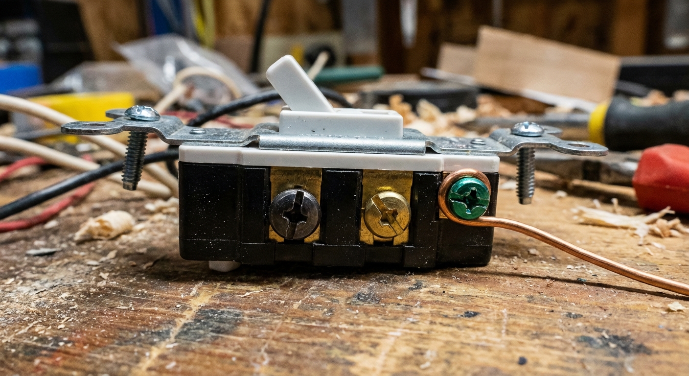
Each 3-way switch has:
- One common terminal (usually a darker screw, often black). This is the special one. It is not neutral and it is not ground.
- Two traveler terminals (usually brass screws). These two terminals connect to the traveler wires running between the two switches.
- A ground terminal (green screw).
When you flip either switch, it changes which traveler is connected to the common. With two switches doing that, the circuit can either complete the path to the light or break it.
Traveler vs common
Traveler wires
The travelers are the two wires that run between the two 3-way switches. In modern cable, they are often red and black inside a 3-conductor cable (like 14/3 or 12/3). But colors are not a guarantee. Someone could have re-marked wires or used different cable.
Common wire
The common screw on a 3-way switch is the odd one out. On one switch, the common will be connected to the incoming hot (line). On the other switch, the common will be connected to the wire that goes to the light (load or switch leg). Which switch is which depends on how the house was wired.
Neutral wires
Neutrals (usually white) often bypass the switches entirely and are tied together in the back of a box. In some older or alternate layouts, a white wire may be used as a hot conductor as part of a switch loop. If that happens, it should be re-identified with black tape or marker. Treat any re-identified white as hot.
Tip: If you are re-identifying a white-as-hot, do it with tape on both ends anywhere it is accessible (in the switch box, fixture box, and any open junctions). That way the next person is not guessing.
Before you start
Tools and supplies
- Non-contact voltage tester (and ideally a two-pole tester or multimeter for confirmation)
- Flathead and Phillips screwdrivers
- Needle-nose pliers
- Wire strippers
- Wire connectors (wire nuts) and electrical tape
- New 3-way switch (not single-pole)
- Optional but helpful: phone camera, masking tape, marker
Match wire size and device listing
Check the breaker size and the wire gauge. 15 amp circuits typically use 14 AWG. 20 amp circuits typically use 12 AWG.
For the switch itself, use a device that is listed and marked for the circuit and application. Many common snap switches are marked 15A, but are also listed for general-use switching on 20A lighting circuits. Do not guess. Read the markings on the device and match what is installed when possible.
Two common setups
There are a lot of variations in the field, but most DIYers run into one of these two big-picture configurations:
- Power-at-switch: the hot feed enters one of the switch boxes first.
- Power-at-light: the hot feed enters the light fixture box first, then a cable runs down to the switches.
Below are plain-English wiring layouts you can use to understand what you are looking at. Use them as concepts, not as a promise that your wire colors match perfectly. Only tracing or testing can confirm what is what.
Setup A: Power-at-switch
In this setup, the incoming hot (line) and neutral come into one of the switch boxes. The neutral usually never lands on the switches. The hot goes to the common screw of the first switch. Travelers run between switches. The second switch common goes to the light (load).
POWER SOURCE (hot+neutral)
          |
          | (hot)
     [3-way SW #1]
      COM  = LINE (incoming hot)
      T1/T2 = travelers --------------------.
                                             \
                                              \
                                         [3-way SW #2]
                                          COM = LOAD (to light hot)
                                             |
                                             | (switched hot)
                                           [LIGHT]
                                             |
                                         neutral returns to source
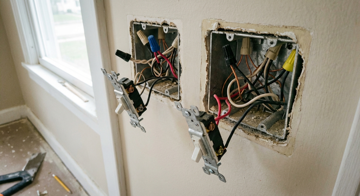
What you typically see in the boxes:
- Switch box with power: a cable from the panel (hot and neutral) plus a cable between switches (two travelers plus ground, and often a neutral pass-through).
- Other switch box: a traveler cable plus a cable to the light.
Setup B: Power-at-light
In this setup, the hot and neutral arrive at the light first. Neutral stays at the light. Hot is sent down to one switch common, then travelers run to the second switch, and the second switch common sends switched hot back up to the light.
There are also older variations that accomplish the same thing using different cable types and re-identified whites. The big picture is the same, but the exact conductor colors can vary.
POWER SOURCE (hot+neutral)
          |
        [LIGHT BOX]
          |  neutral stays here
          |  hot goes down to switch common
          |
     (to SW #1 common)
     [3-way SW #1]
      COM = LINE (from light box)
      T1/T2 = travelers --------------------.
                                             \
                                              \
                                         [3-way SW #2]
                                          COM = LOAD (back to light box)
                                             |
                                      (switched hot back up)
                                             |
                                        [LIGHT BOX]
What you often see: fewer neutrals in the switch boxes, and more splices at the fixture. If your switch box has no neutral bundle at all, this setup is more likely, but it is not definitive.
Replace a 3-way switch
I have replaced enough switches to learn this the hard way: the safest route is to label what is on the common screw before you remove anything. Travelers can swap between traveler screws and still work. The common cannot.
1) Turn off power and verify
- Turn off the correct breaker.
- Test at both switch locations.
- Verify absence of voltage before touching conductors. Non-contact testers are convenient, but they can be fooled. If you have a two-pole tester or a multimeter, use it to confirm.
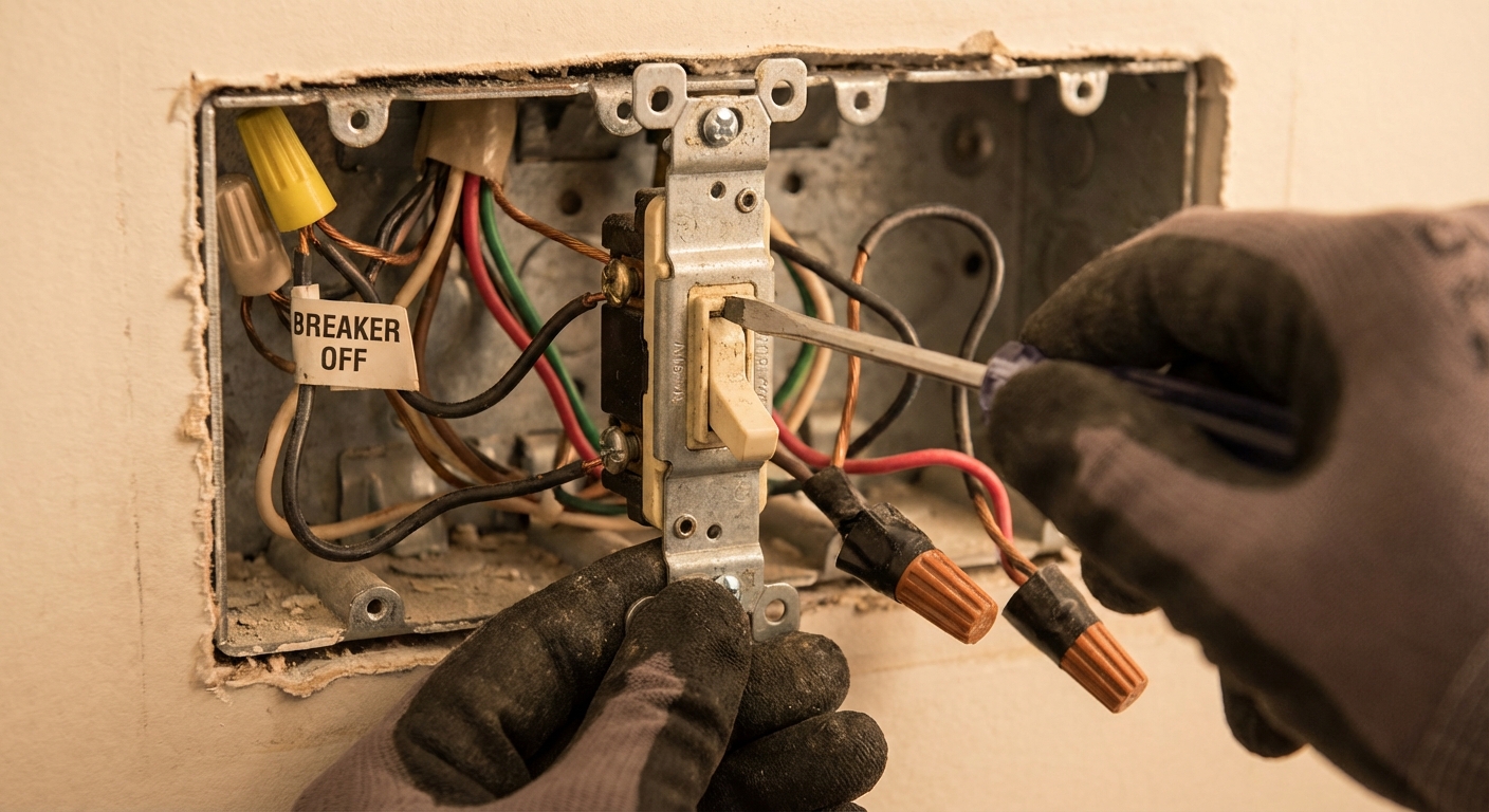
2) Pull the switch out and take a photo
Unscrew the switch mounting screws and gently pull the switch forward. Take a clear photo showing which wire is on which screw. This is your insurance policy.
3) Identify the common wire
Look for the darker screw on the old switch. The wire on that darker screw is the common wire. Mark it with tape labeled COMMON.
If the old switch is back-wired and you cannot easily see the common location, look for markings on the switch body such as COM or a different colored screw. If you still cannot tell, stop and verify with the switch model or call for help.
4) Disconnect wires
Disconnect conductors one at a time and keep them separated so nothing springs back and touches something else. Many people leave the ground connected until the end since it helps keep things referenced. Others remove it first to get it out of the way. Either approach is fine as long as the power is off and your wires stay controlled.
- Disconnect the two travelers (usually on the brass screws).
- Disconnect the common last so you do not mix it up.
- Disconnect the ground when convenient.
If the wire ends are nicked or bent into a messy hook, cut and re-strip to a clean end. A fresh, tight hook makes a better connection.
5) Connect the new 3-way switch
- Attach the marked COMMON wire to the new switch common (dark screw).
- Attach the other two wires to the traveler screws (brass). Order does not matter.
- Attach ground to the green screw. If the box is metal, make sure the box is grounded too.
Pro tip from my own mistakes: wrap clockwise. Form the wire hook so it wraps clockwise around the screw. Tightening the screw then pulls the hook tighter instead of pushing it out.
About push-in connections: avoid the simple push-in backstab holes on basic switches. They are more failure-prone over time. Some higher-end devices use a back-wire clamp plate that tightens with a screw, and those are generally solid. When in doubt, use the side screws and make a good, tight termination.
6) Reinstall neatly
- Fold wires back carefully. Do not crush insulation.
- Mount the switch upright and snug the screws.
- Reinstall the wall plate.
7) Restore power and test
Turn the breaker back on. Test the light from both switches in multiple positions. A proper 3-way circuit will let either switch change the state of the light no matter where the other switch is set.
Mistakes that break it
Mixing up common and traveler
This is the big one. If the common wire lands on a traveler screw, the circuit will act weird or fail completely. Symptoms include:
- Light only works in one specific combination of switch positions
- One switch seems to do nothing
- Light flickers or is unreliable (especially if a connection is loose)
Assuming white is neutral
In some switch loop setups, a white wire is used as a hot conductor. It should be re-marked black, but that does not always happen. Do not automatically tie whites together unless you are sure they are neutrals in that box.
Using a single-pole switch
A single-pole switch has two terminals plus ground. A 3-way has three terminals plus ground. If you install a single-pole in a 3-way circuit, you will not get correct operation.
Loose connections
Loose terminations cause heat and intermittent failures. Tight, solid connections win every time.
Not grounding
A missing ground might not stop the light from working, but it is a safety problem. Always connect the ground to the switch and ensure the box is grounded per your wiring method.
Mixing travelers in a busy box
In multi-gang boxes, it is common to have multiple switch loops and sometimes multiple 3-way circuits in the same box. Be careful not to grab one traveler from one cable and one traveler from another. Keep each traveler pair together as a set from the same 3-conductor cable.
Troubleshooting
If you replaced a switch and now the 3-way is dead or acting wrong, work through this checklist.
1) Confirm it is a 3-way
Look for 3-way on the strap or packaging, and confirm there is one darker common screw and two traveler screws.
2) Re-check the common
Shut power off. Pull the switch back out. The wire you labeled as common must be on the dark screw. If you did not label it, compare to your photo of the old switch.
3) Verify the traveler pair
Travelers can swap positions on traveler screws, but you cannot replace one traveler with a different conductor that is not part of the traveler cable. If the box has multiple cables, confirm you used the correct pair.
4) Check neutrals and splices
If neutrals are loose at the fixture or in a switch box, the light may be dead even if the switching is correct. With power off, tug-test wire nuts gently and redo any questionable splices.
5) Rule out a bad switch
Brand-new switches can be defective. If wiring is verified and connections are tight, swapping in another 3-way switch can rule this out.
Smart switches and code
Many smart 3-way switches require a neutral in the box. Some older 3-way setups do not have one. If you open the box and only see a couple insulated conductors and a ground, you may need a different smart switch style (that does not require neutral) or you may need an electrician to reconfigure wiring.
Modern electrical codes in many areas require a neutral at many switch locations for new work, with exceptions. Requirements vary by jurisdiction and by the code edition your area has adopted, so treat this as a planning tip, not a guarantee.
Quick recap
- A 3-way switch has one common and two travelers, plus ground.
- The common screw (dark) is the one that matters most. Label that wire before removing anything.
- There are two common layouts: power-at-switch and power-at-light, plus variations.
- Most failures come from mixing up the common, misidentifying a white wire, mixing traveler pairs in a busy box, or leaving a loose connection.
If you want, tell me what wires you see in each box (how many cables enter, and the colors present). I can help you map which setup you likely have before you make any connections.
About Marcus Vance
Content Creator @ Grit & Home
Marcus Vance is a lifelong DIY enthusiast and self-taught home renovator who has spent the last decade transforming a dilapidated 1970s ranch into his family's dream home. He specializes in budget-friendly carpentry, room-by-room renovations, and demystifying power tools for beginners. Through his writing, Marcus shares practical tutorials and hard-learned lessons to help homeowners tackle their own projects with confidence.